
How to check fit and access
Confirm panel handling weight, removal order, nozzle clearance and access to bolts and lifting points.
See inspection and acceptance checks →Equipment & process
Plan sections around nozzle positions and the head removal path.
Shell-and-tube exchanger heads opened for cleaning or tube bundle service.

Compare alternate views and see how the jacket opens, fits or fastens.
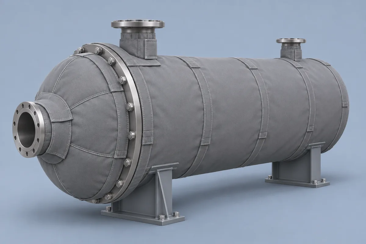
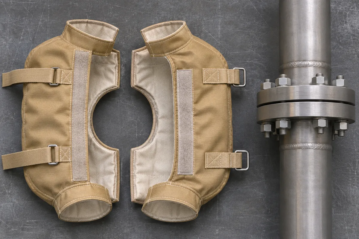
Dividing the head into panels gives the maintenance team a manageable removal sequence without covering lifting or bolting points.
These are options for a custom quotation. Confirm the assembled materials, dimensions, service limits and finish in writing.
inspect lining, end collars and the space needed for bolt access.
Compare the product views above ↑
Industry construction reference → · Aerogel stock thicknesses
Assess large-area heat loss and hotspots around penetrations and the head-to-shell junction.
Agree the conditions, measurement points and target for the proposed cover before quoting. Record the complete assembly’s approved service limits separately from the target outside-face temperature.
Compare thickness, surface temperature and heat loss →Calculated outside-face temperature for Shannon LT450SS at 21.1 °C ambient, flat-surface model. The manufacturer lists a maximum service temperature of 232 °C for this model. The columns show its nominal insulation thicknesses in millimeters and the manufacturer’s approximate inch equivalents.
| Operating temperature | 25 mm (1 in) | 40 mm (1½ in) | 50 mm (2 in) |
|---|---|---|---|
| 121 °C | 37.9 °C | 33.3 °C | 30.8 °C |
| 177 °C | 47.3 °C | 40.3 °C | 36.3 °C |
| 232 °C | 57.2 °C | 47.8 °C | 42.3 °C |
These figures describe the cited manufacturer’s model. Shape, airflow, compression, gaps and closures affect the installed result. A lower outside-face temperature still needs to be checked against your site’s contact and inspection requirements.
Read the manufacturer’s data →Confirm panel handling weight, removal order, nozzle clearance and access to bolts and lifting points.
See inspection and acceptance checks →Send head profile, nozzle projection, bolt ring dimensions and lifting and access plan.
Include a drawing or scaled photos, quantity and delivery location. Once the key measurements are available, we can review a CAD drawing or annotated design together.