TERCCIndustrial insulation by TERUURequest a Quote
Removable insulation

Reference Design Gallery

Compare design renderings by equipment, closure and maintenance access. Select references to include with your measurements or drawing.

Showing 12 of 12 concept reference designs.
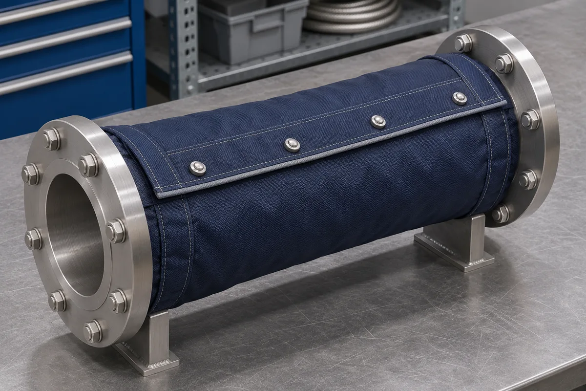
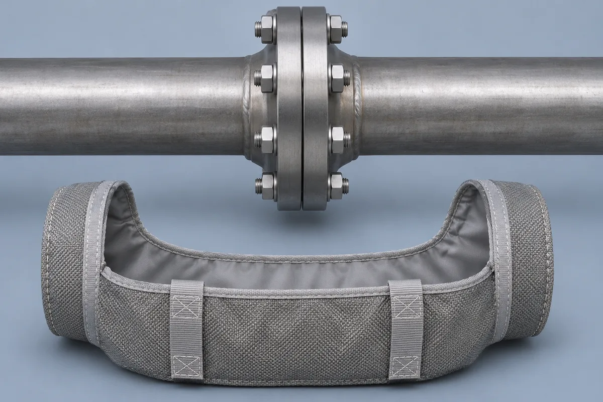
Split-Ring Flange Cover Concept
Open-access concept with the bolt ring exposed · Design illustration
TERCC-RD-005

Split-Ring Flange Cover Concept

Two shaped sections enclose the flange pair. Specify the pipe-end collars, bolt projections and space to lift the cover away.
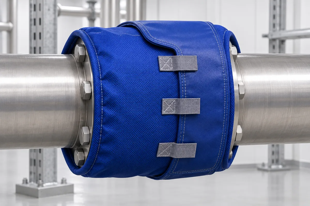
Split ringFlange
View details
Wraparound Band Flange Concept
Design illustration
TERCC-RD-006

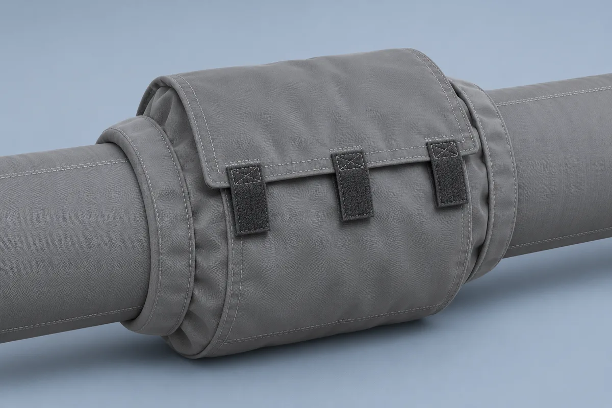
Wraparound Band Flange Concept

A flexible band wraps the flange pair with an overlapping closure. Check the adjoining pipe insulation and access to the fastening tabs.
Wraparound bandFlange
View details
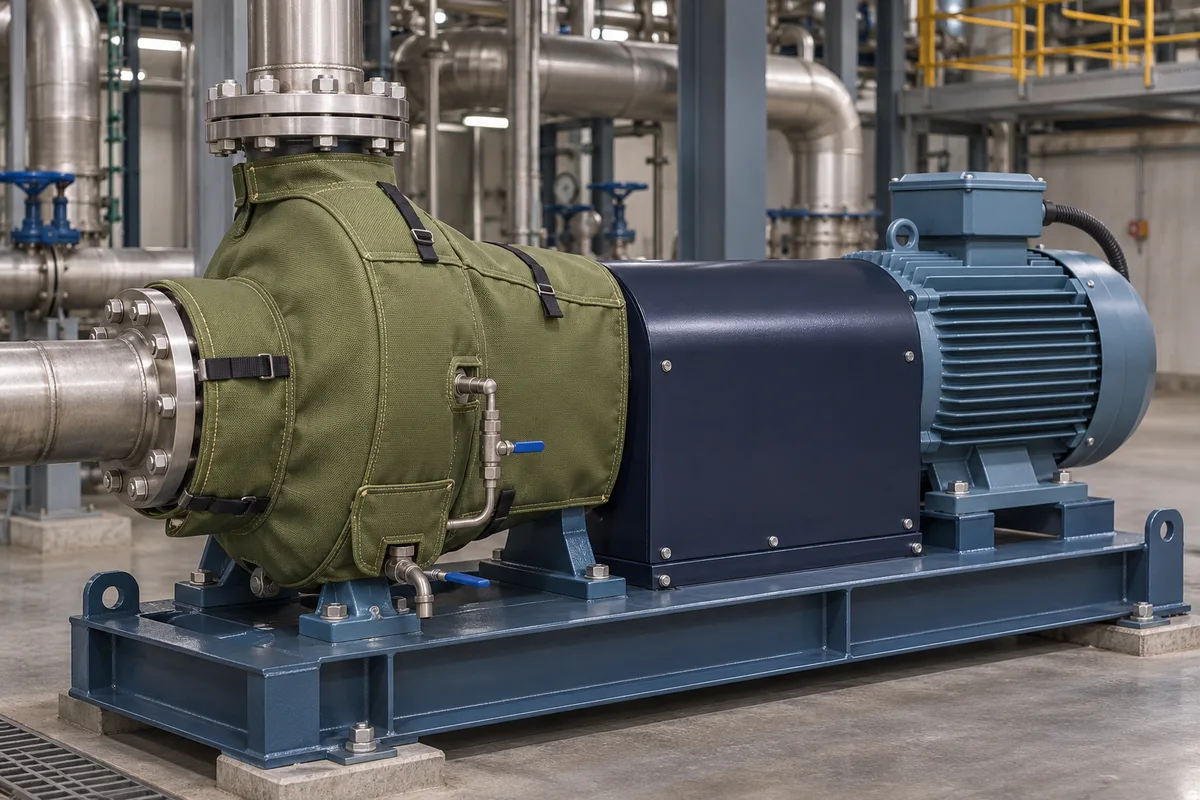
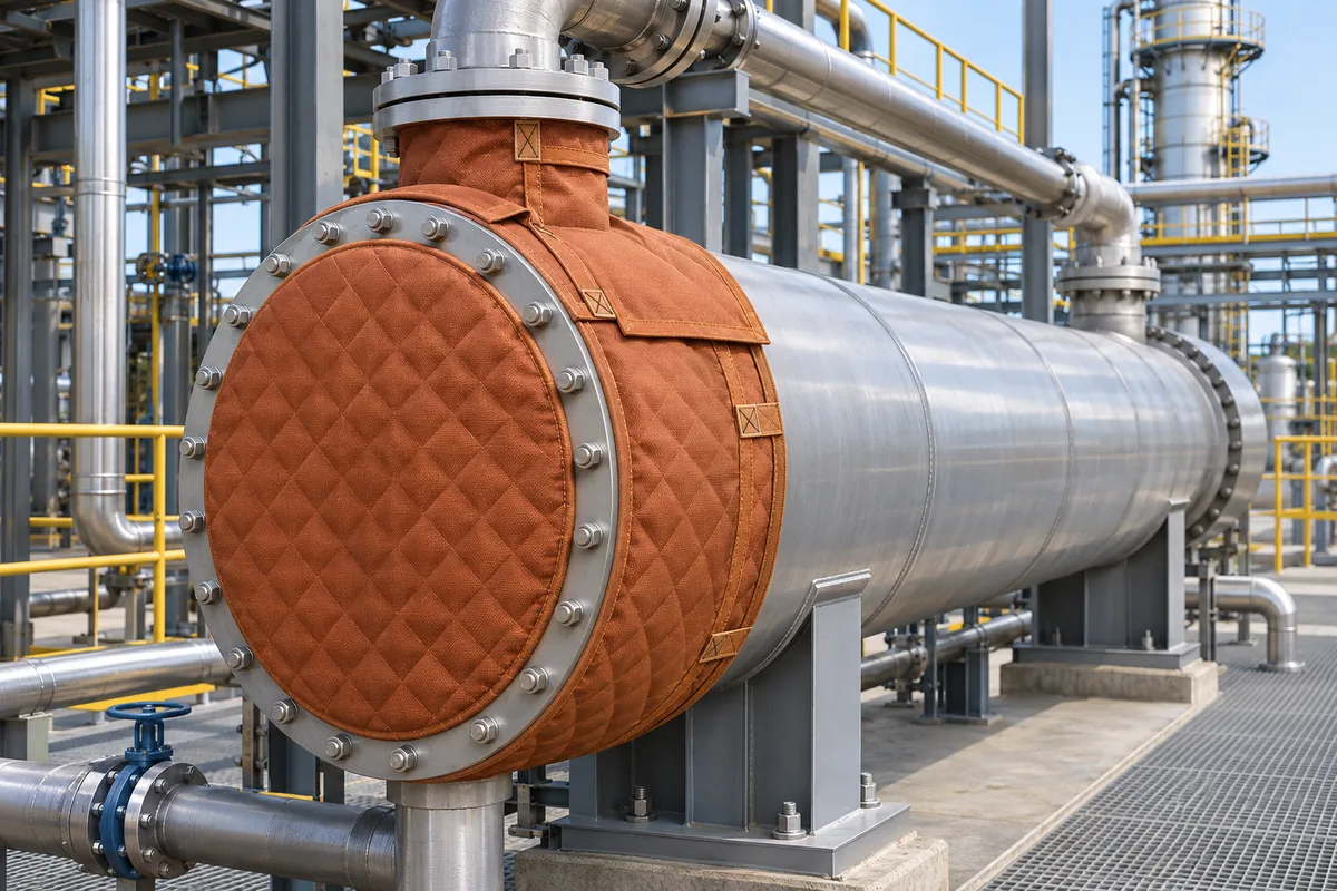
Pump Envelope — Discussion Sketch
Design illustration
TERCC-RD-010

Pump Envelope — Discussion Sketch

A removable cover concept for the pump casing. Confirm clearances around the motor, coupling guard, flanges and inspection points.
Enclosure-stylePump
View details
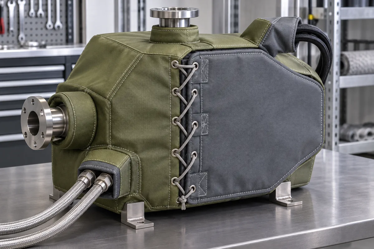
Custom OEM Enclosure-Style Concept
Design illustration
TERCC-RD-012

Custom OEM Enclosure-Style Concept

A tailored enclosure for irregular equipment. Mark the connector cutouts, access openings and removal direction on the drawing.

Enclosure-styleCustom / OEM
View details

Studio and alternate views

Compare closures, access openings and cover shape across equipment types.
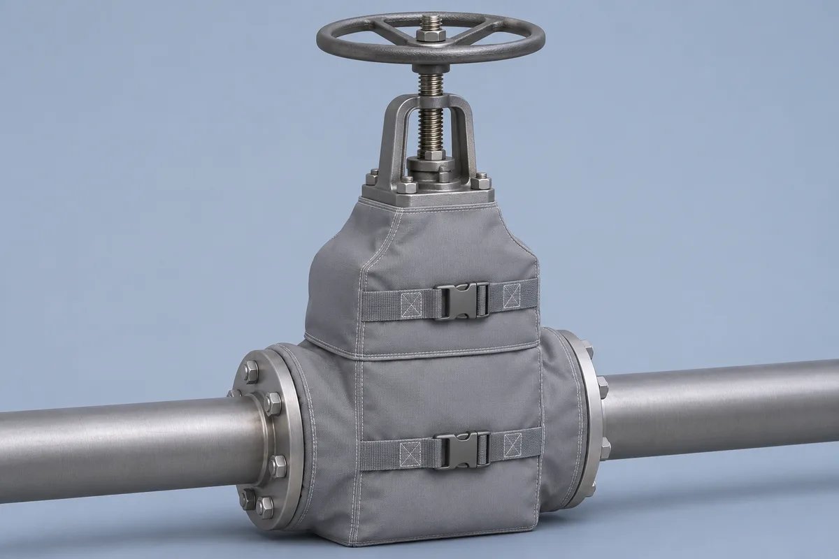
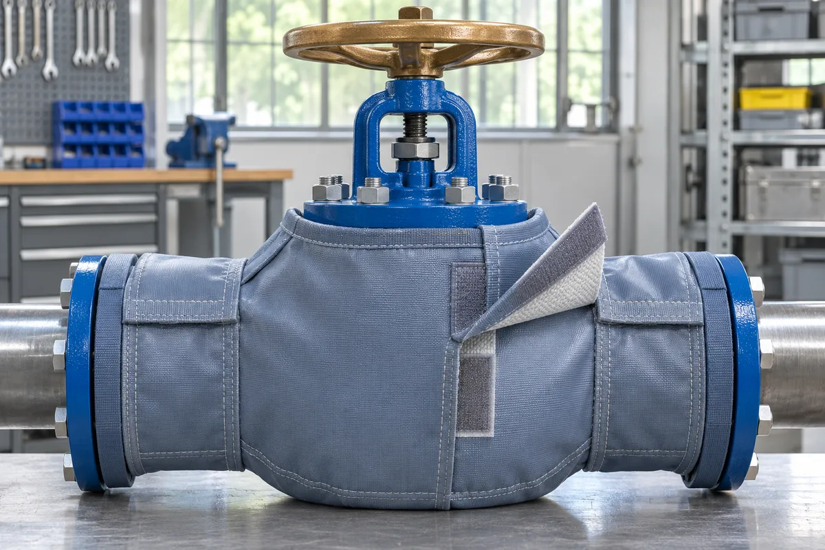
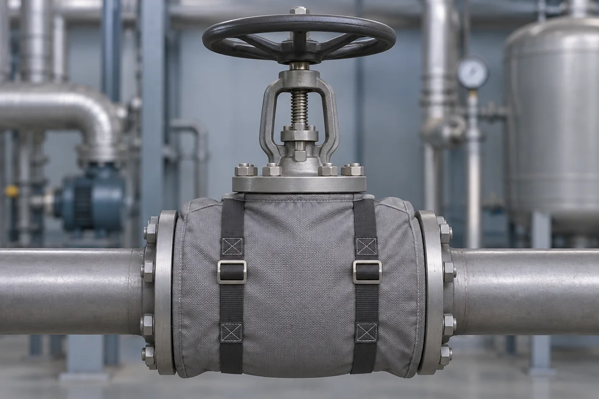
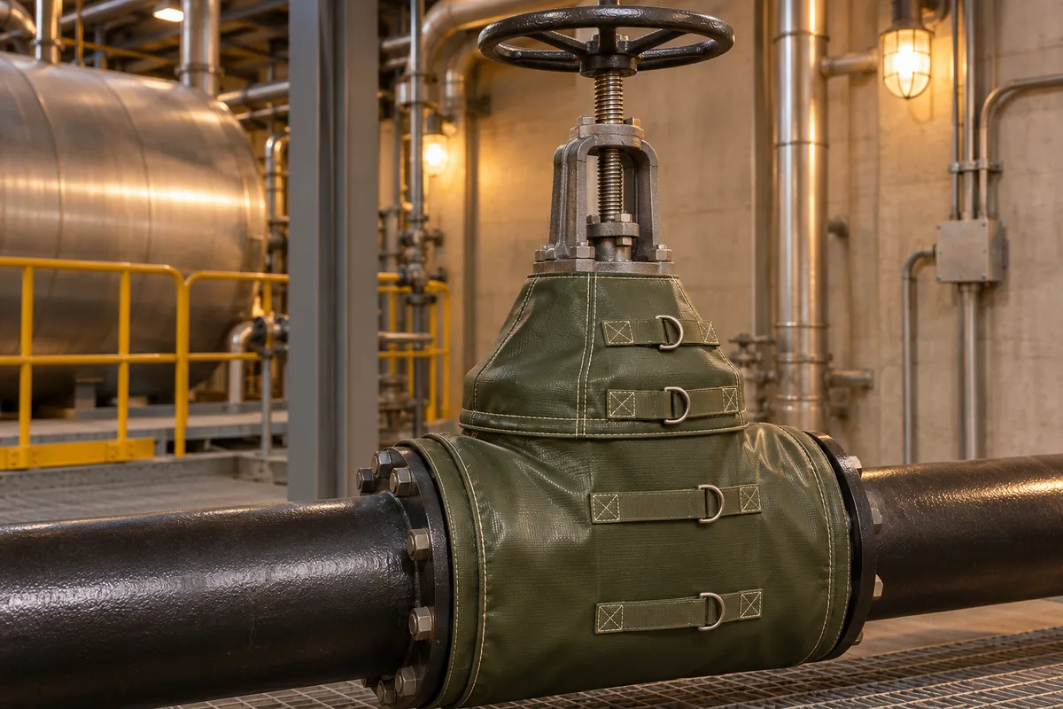
Gate valve with a two-section gray jacket and exposed rising stem
Alternative design · studio view · Design illustration
Open image ↗
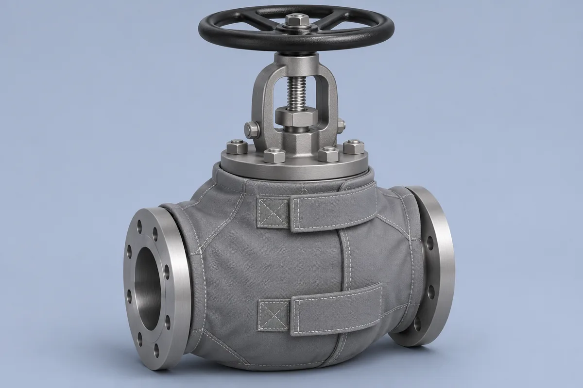
Handwheel valve with a fitted gray jacket secured by two webbing straps
Strap and handwheel view · Design illustration
Open image ↗
Globe valve with shaped gray panels and clearance around the stem
Alternative design · studio view · Design illustration
Open image ↗
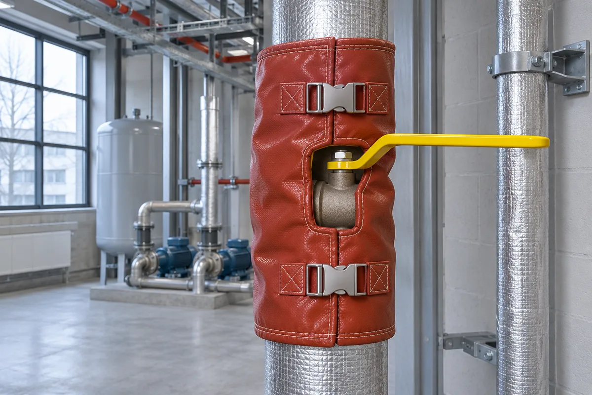
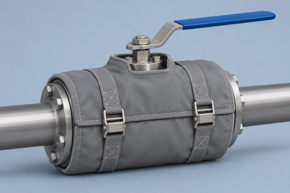
Split gray cover on a quarter-turn valve with exposed lever
Alternative design · studio view · Design illustration
Open image ↗
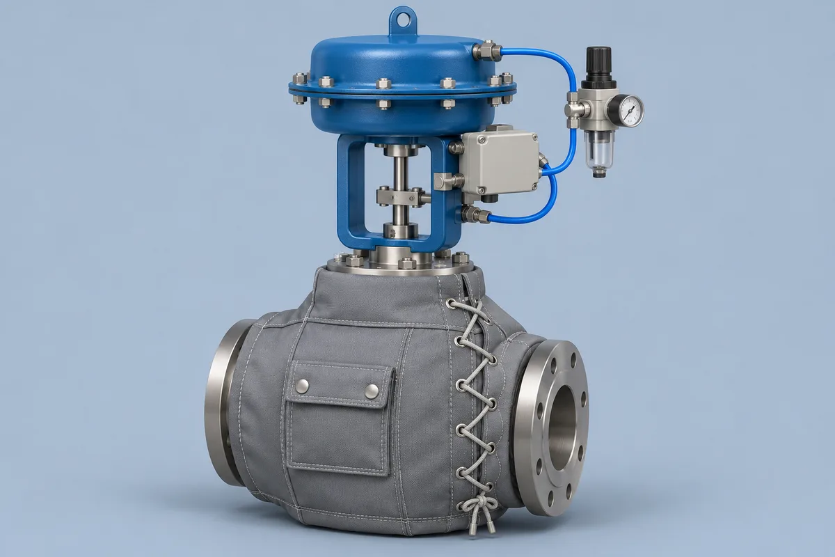
Laced gray jacket with a service flap and a blue actuator outside the cover
Alternative design · studio view · Design illustration
Open image ↗
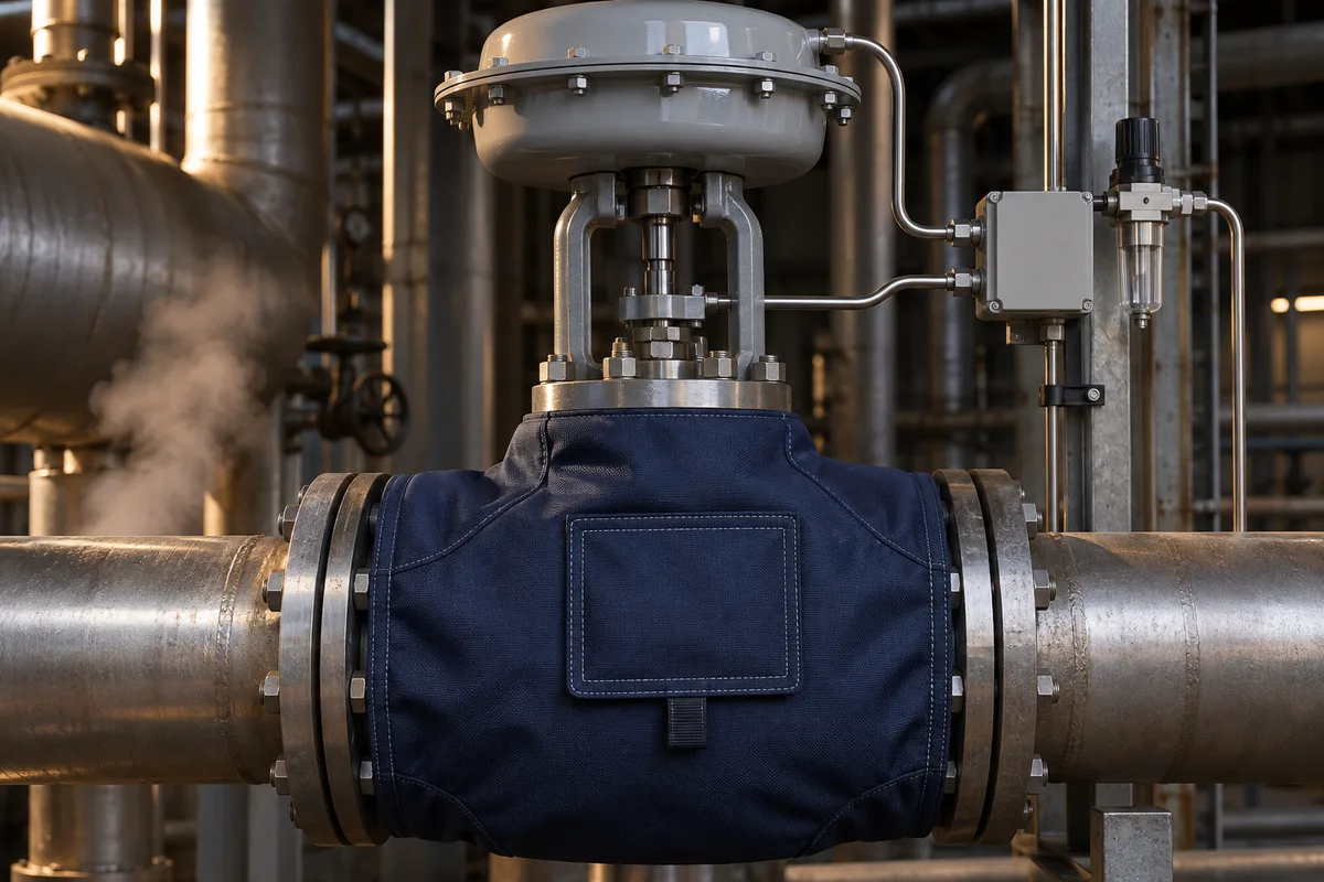
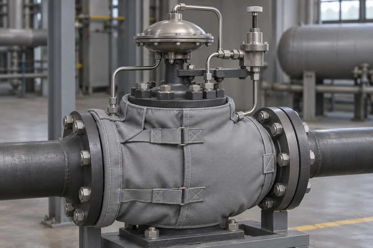
Pressure-reducing valve jacket with the dome and pilot lines outside the cover
Alternative design · installed view · Design illustration
Open image ↗
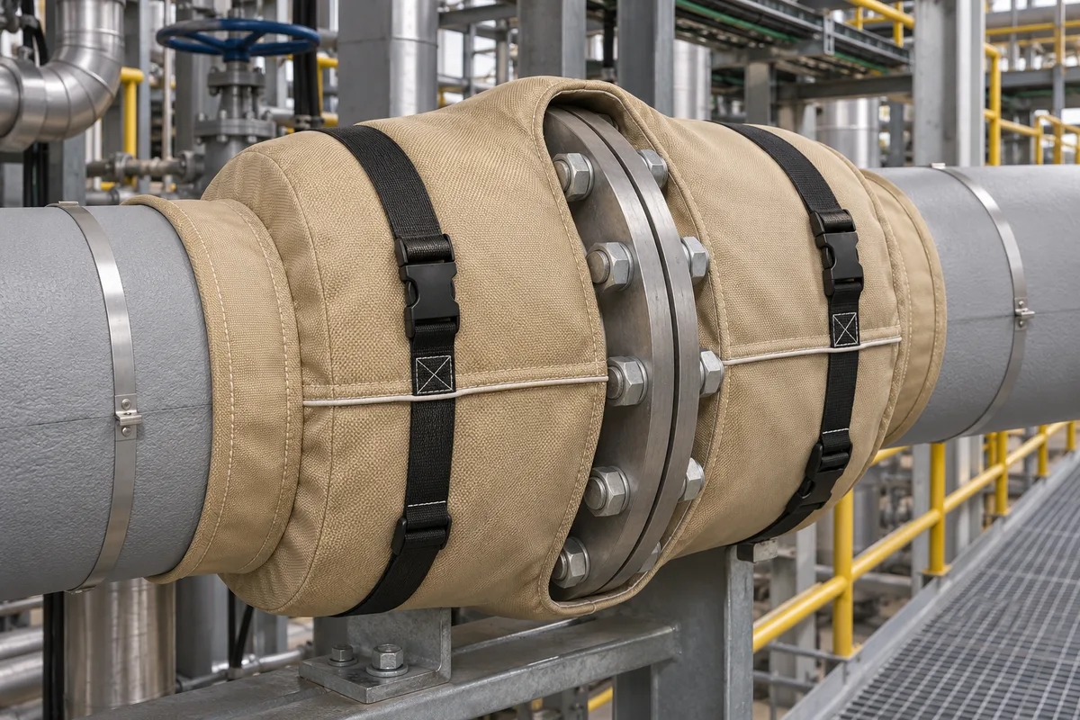
Shaped split flange jacket with straps and collars around the pipe
Alternative design · studio view · Design illustration
Open image ↗
Open flange cover showing the lining and exposed bolts
Cover removed · Design illustration
Open image ↗
Gray flexible flange wrap with overlapping closure tabs
Alternative design · studio view · Design illustration
Open image ↗
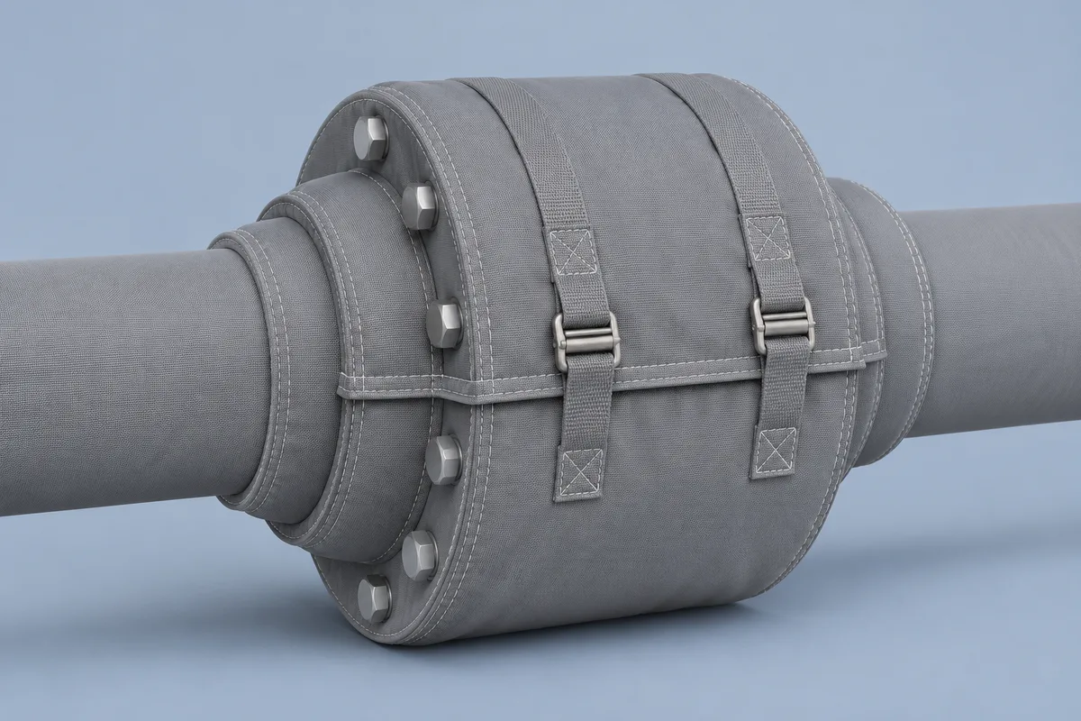
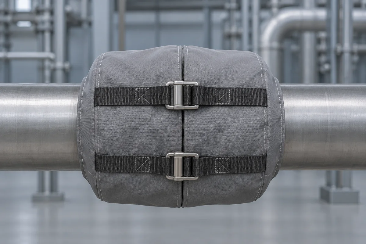
Round gray flange wrap with an overlap and two buckled straps
Alternative strap closure · Design illustration
Open image ↗
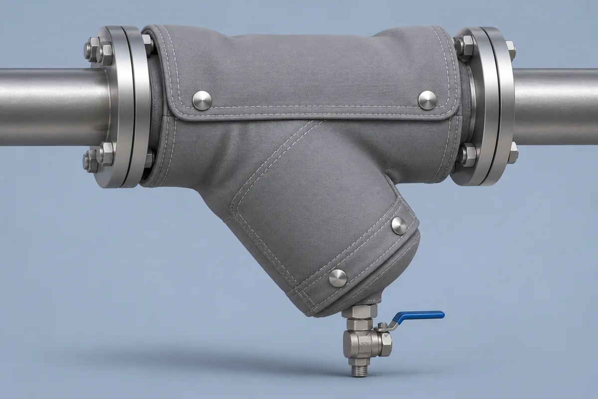
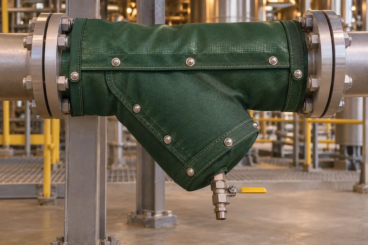
Shaped gray cover following a strainer branch with the drain exposed
Alternative design · studio view · Design illustration
Open image ↗
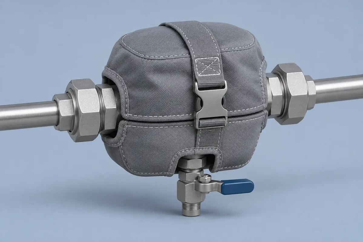
Compact steam-trap cover with exposed unions and service connection
Alternative design · studio view · Design illustration
Open image ↗
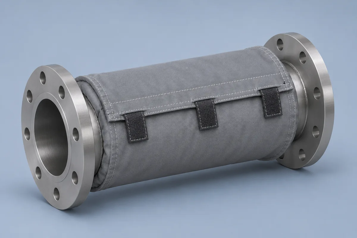
Gray cylindrical pipe sleeve with both end flanges accessible
Alternative design · studio view · Design illustration
Open image ↗
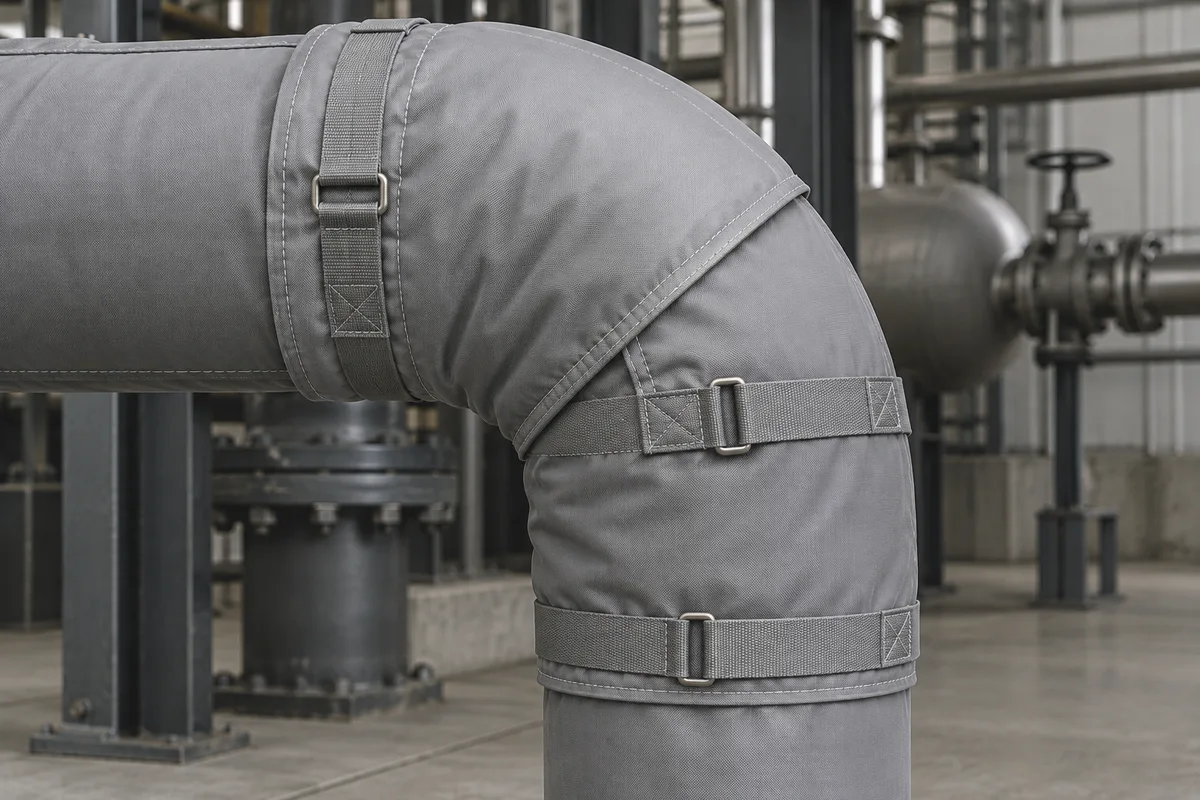
Removable gray cover following a pipe elbow with a visible split seam
Alternative design · installed view · Design illustration
Open image ↗
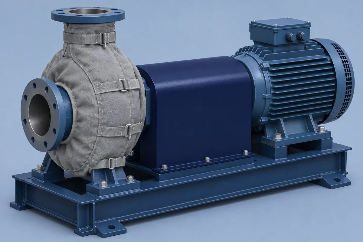
Pump casing cover with separate coupling guard and uncovered motor
Alternative design · studio view · Design illustration
Open image ↗
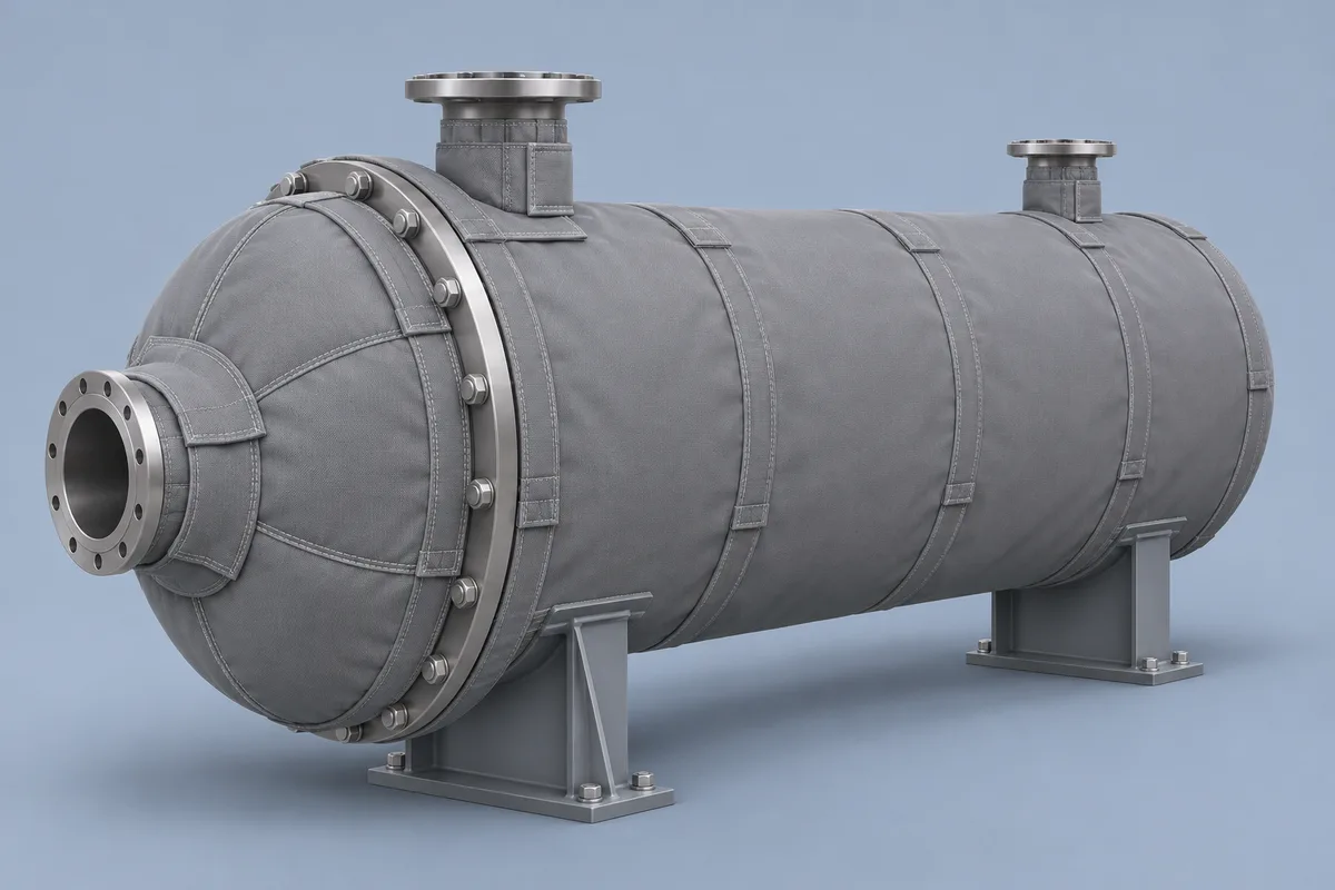
Alternative exchanger concept showing removable head and shell coverage
Alternative design · studio view · Design illustration
Open image ↗
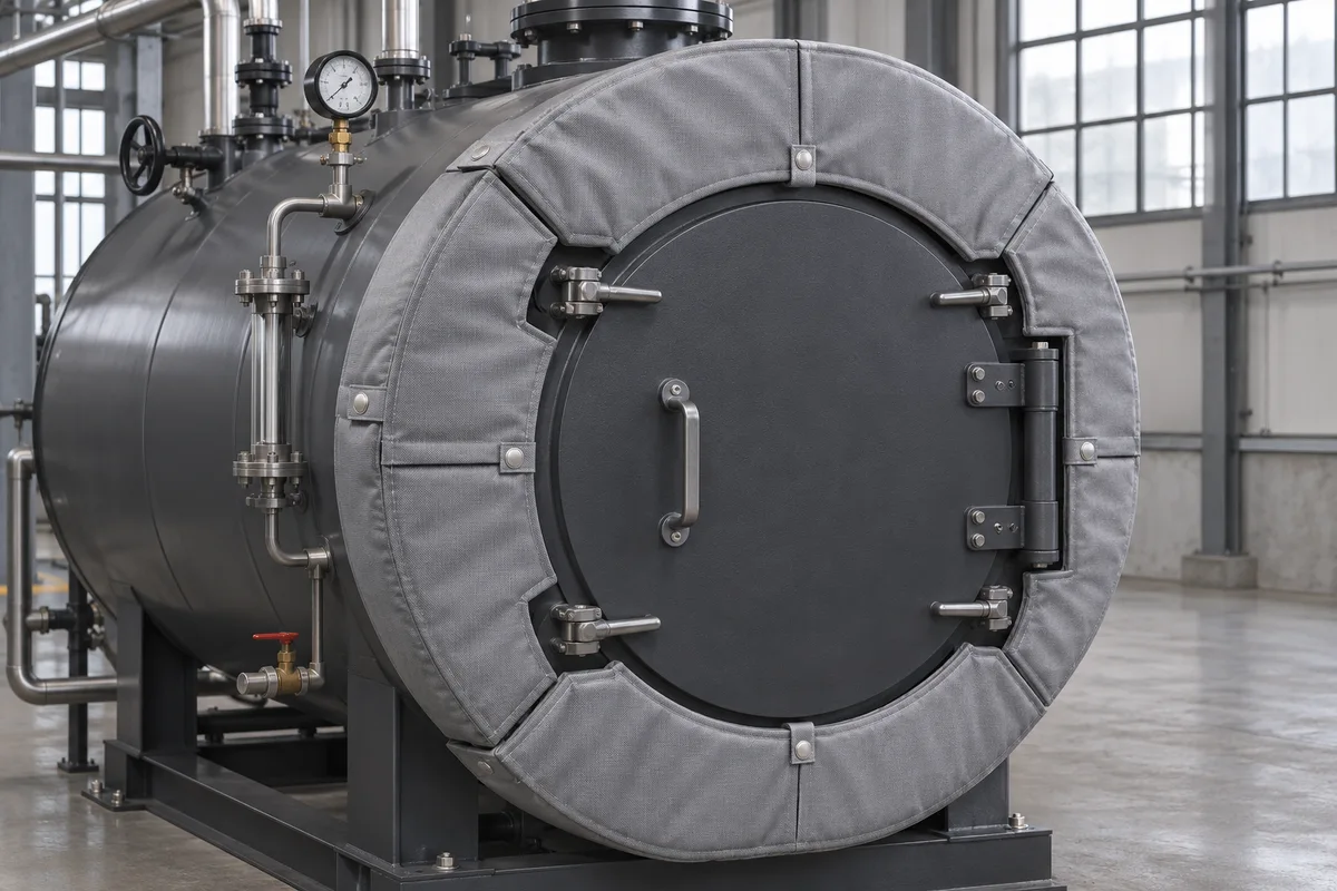
Gray insulation panels around a circular boiler access door
Alternative design · installed view · Design illustration
Open image ↗
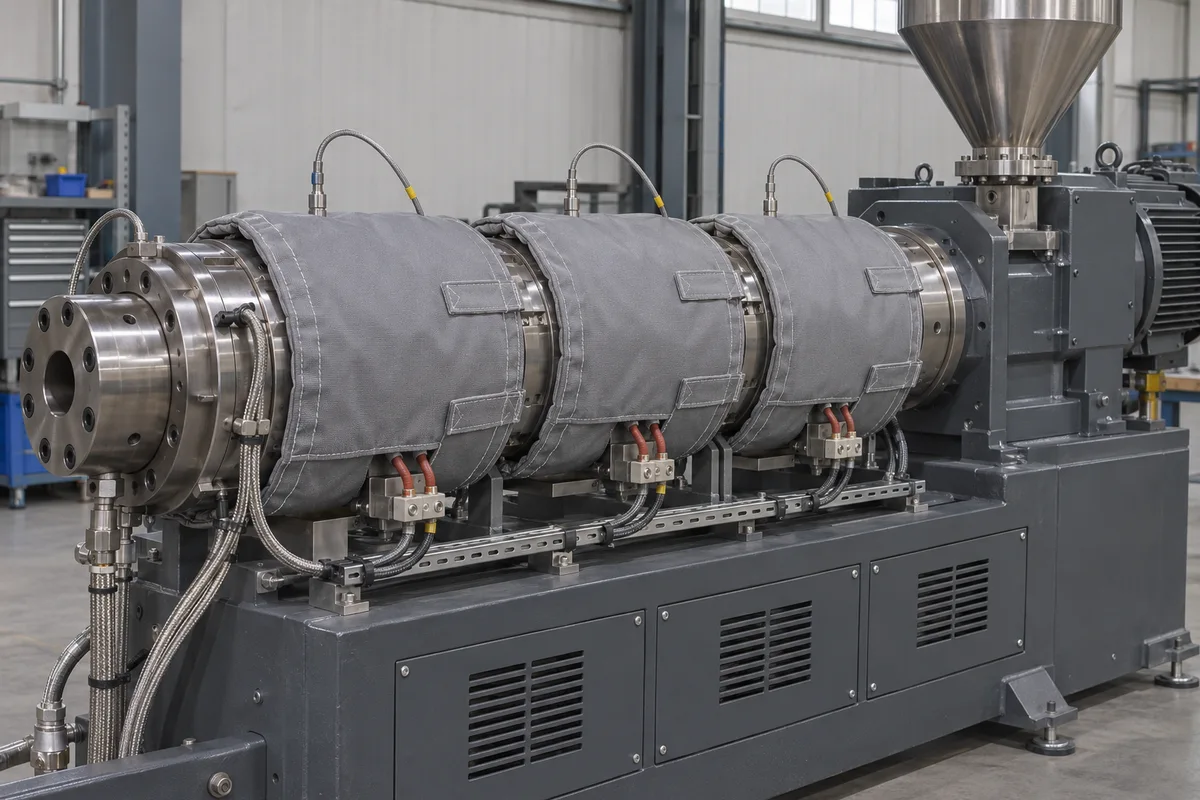
Three gray insulation bands on separately accessible extruder heater zones
Alternative design · installed view · Design illustration
Open image ↗
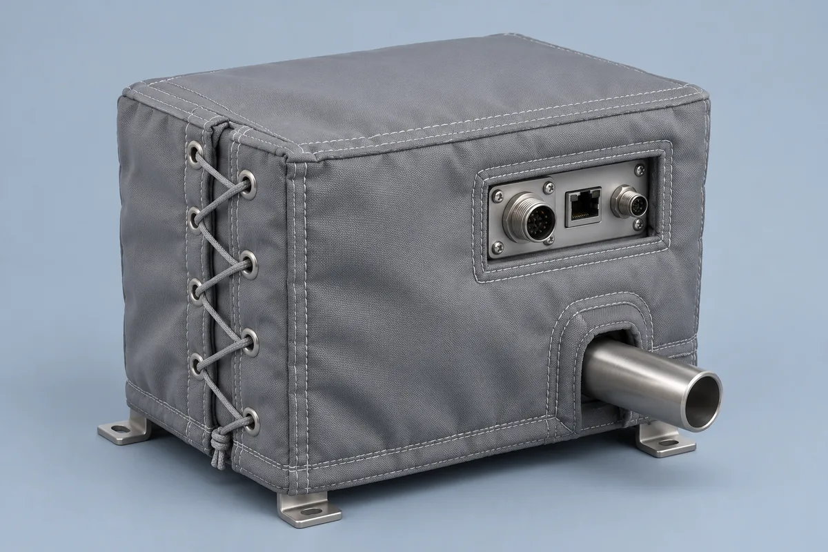
Gray insulated equipment enclosure with side lacing and connector cutouts
Alternative design · studio view · Design illustration
Open image ↗
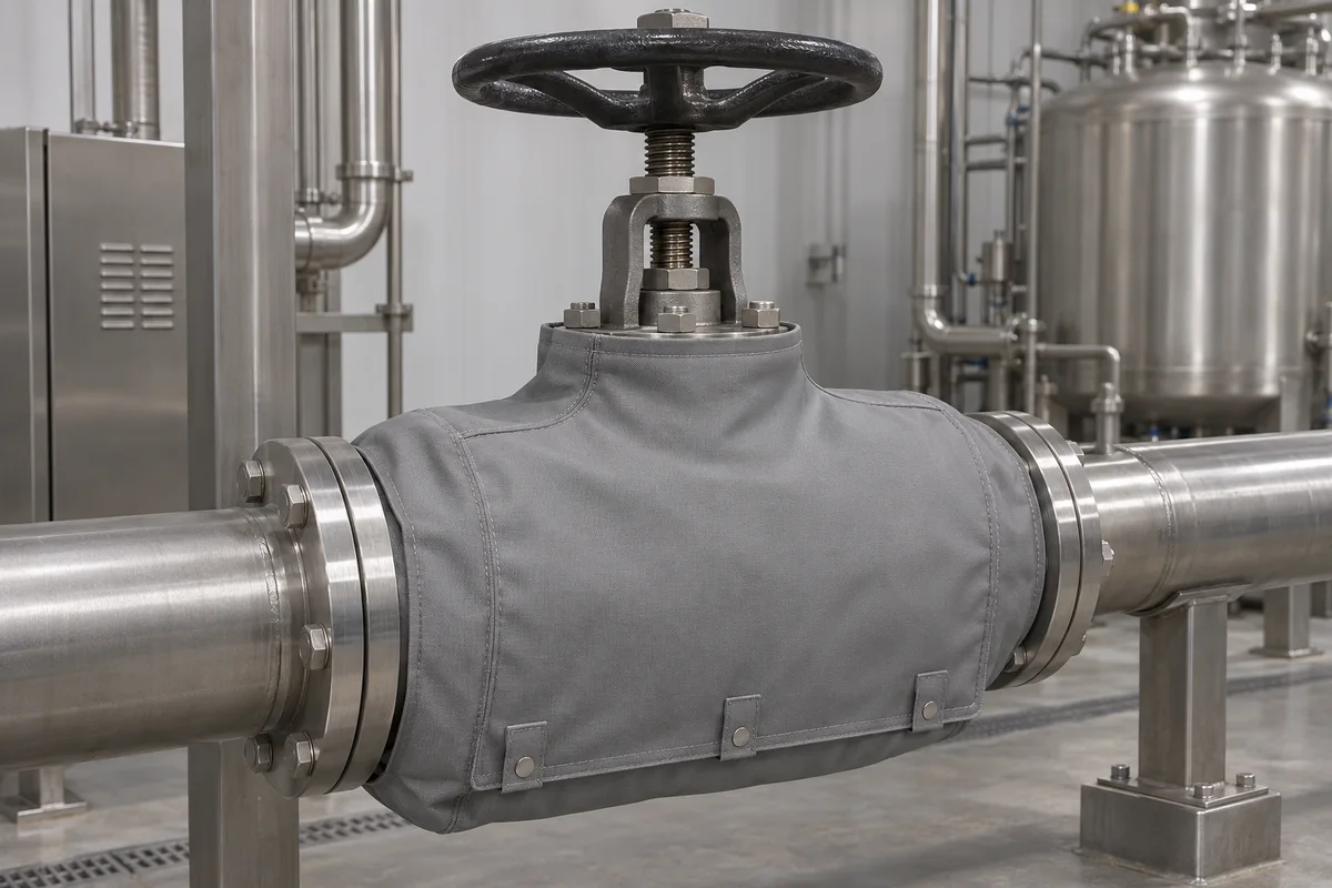
Smooth gray utility valve cover with the handwheel and stem exposed
Alternative design · installed view · Design illustration
Open image ↗
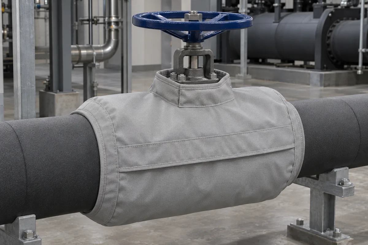
Chilled-water valve jacket concept with an overlap and adjacent pipe insulation
Alternative design · installed view · Design illustration
Open image ↗

Equipment photos and diagrams

Use these third-party references to identify fittings, service points and the space around installed equipment.
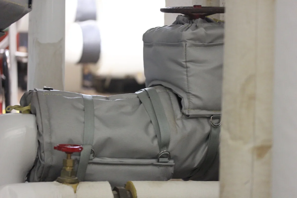
A fitted removable insulation blanket installed on industrial equipment
Third-party installation photo · A removable insulation blanket fitted to industrial equipment. Removable Insulation Blanket.jpg by Christopher Vella / Wikimedia Commons · CC BY-SA 4.0 · Resized and converted to WebP
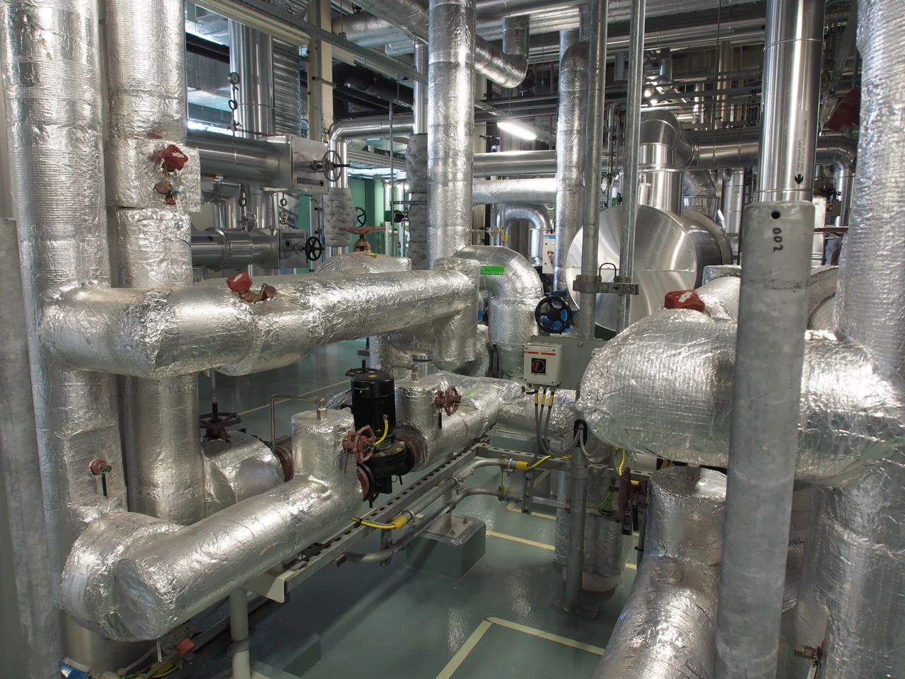
Industrial plant with insulated pipes and several bends at different elevations
Application reference photo · Insulated pipework in an industrial plant. Piping pic1 by Alf van Beem / Wikimedia Commons · CC0 1.0 · Resized and converted to WebP
Industrial valve with an exposed stem and bolted flanges
Equipment reference photo · Valve body, projecting stem and flange connections. Válvula industrial by Rjcastillo / Wikimedia Commons · CC BY-SA 3.0 · Resized and converted to WebP
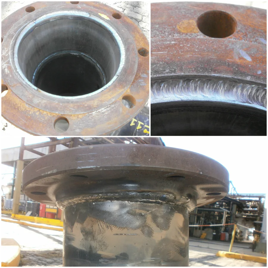
Three views of a welded slip-on pipe flange showing the face and bolt holes
Equipment reference photo · Slip-on flange face, bolt holes and pipe connection. Slip On Flange doubled welded by Maggilautaro / Wikimedia Commons · CC BY-SA 4.0 · Resized and converted to WebP
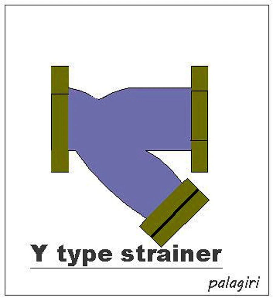
Y-strainer diagram showing the inclined branch below the main line
Equipment diagram · The branch geometry helps locate the space needed to withdraw the screen. Y type strainer by Palagiri / Wikimedia Commons · CC BY-SA 4.0 · Resized and converted to WebP
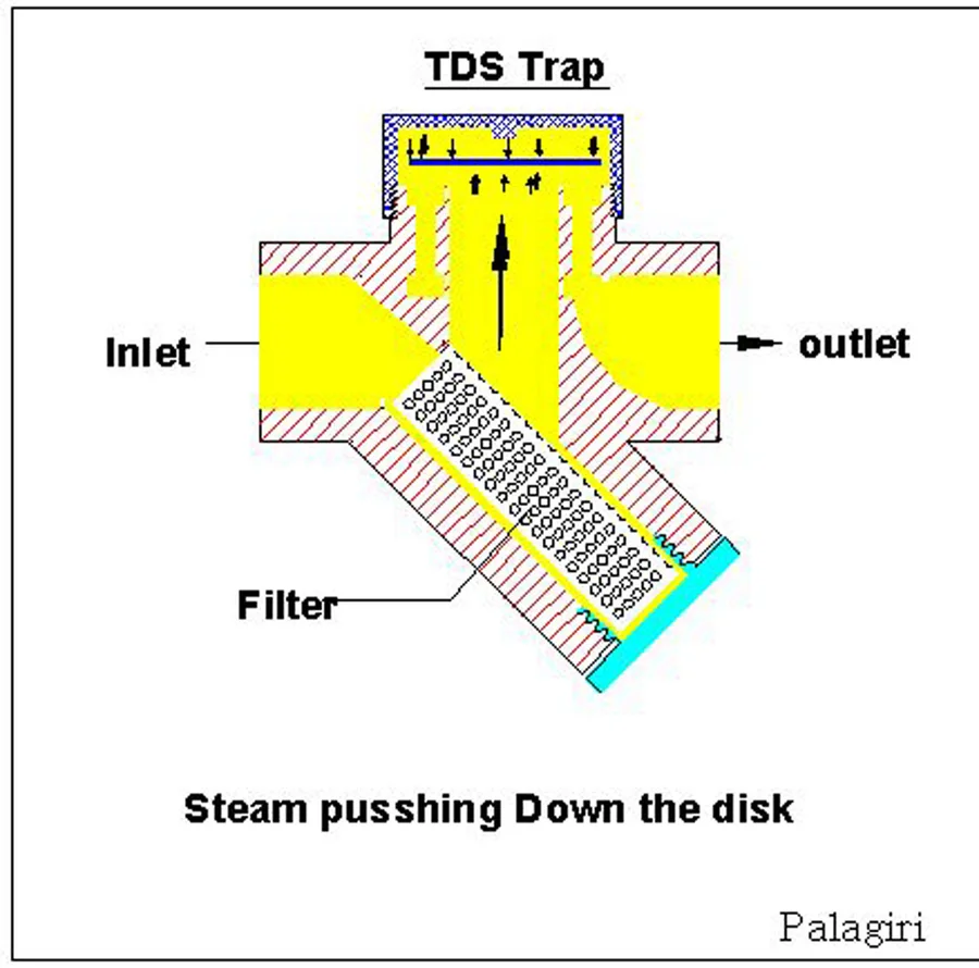
Thermodynamic steam trap cross-section showing inlet, outlet and filter
Equipment diagram · Identify the trap type and follow the installed model’s instructions. TDS Trap -2 by Palagiri / Wikimedia Commons · CC BY-SA 4.0 · Resized and converted to WebP
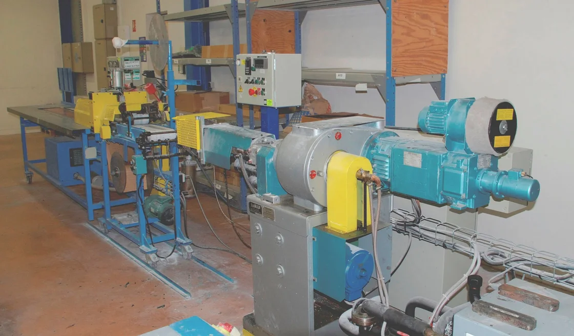
Industrial plastics extruder on a workshop floor with the motor, barrel and dies visible
Equipment context photo · A plastics extruder in a workshop. Plastic extruder.jpg by Cjp24 / Wikimedia Commons · CC BY-SA 3.0 · Resized and converted to WebP
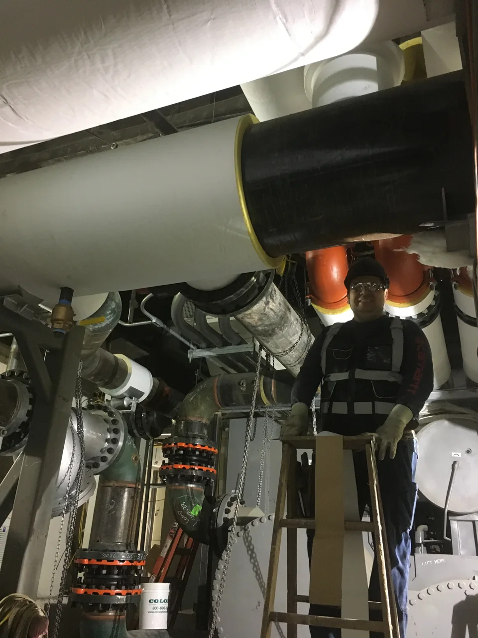
Overhead pipe insulation being installed in an operating-area chiller room
Installation context photo · Pipe insulation work in a chiller room. Installation of pipe insulation in the chiller room by MTA Capital Construction Mega Projects / Wikimedia Commons · CC BY 2.0 · Resized and converted to WebP
How to use a reference

Select a reference for your equipment

Tell us what the cover needs to fit and which components need to stay accessible.

Three steps

  1. Filter by equipment, scenario, structure, fastening, removability or use.
  2. Add one or more TERCC-RD codes to the selection tray.
  3. Continue to one RFQ and add your drawing, photos or item schedule.
Request a Quote →